
Samuel Clay is a grad student in the schools of design and of engineering at Harvard. He founded NewsBlur, a personal RSS news reader, and Turn Touch, beautiful control for the smart home.
Talk to him @samuelclay.
Samuel Clay is a grad student in the schools of design and of engineering at Harvard. He founded NewsBlur, a personal RSS news reader, and Turn Touch, beautiful control for the smart home.
Talk to him @samuelclay.
This was my second year attending Burning Man. Many use Burning Man as a week to detach from their workweek and experience a new life of intense leisure. Not me, I come to Burning Man to build.
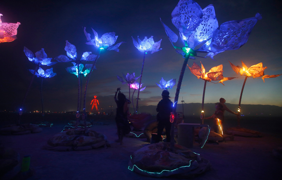
Pulse & Bloom is a 2014 honorarium installation. The core team of 6 people — Saba Ghole, Shilo Shiv Suleman, Rohan Dixit, Heather Stewart, Luke Iseman, and myself — built 20 interactive lotus flowers made out of steel and rowlux. Each lotus flower ranges from 8 to 18 feet tall, each of which lights up with your pulse. You and another person can put your hands on a couple of Hamsa hands at the base of the lotus flower and your respective heartbeats will light up the flower.
We’ve gotten some great press coverage at the BBC, The Guardian, The Atlantic’s Big Picture twice, CBS News, NBC News, and MSNBC.
As usual, the complete source code for Pulse & Bloom is on GitHub.
Here are a couple videos of all twenty lotus flowers in full working order.

Each lotus flower is blue until a person or two sits down at its base and places their hand on the pulse sensor. You can see the Hamsa hand and its embedded pulse sensor in this shot of my girlfriend Brittany and me working on keeping the electronics going.

When a pulse is read, the lotus flower shoots the heartbeat up the stem and into the petals, where it blooms in a brilliant display of amber. When two people’s hands are being measured, both of their heartbeats are shown as two distinct colors.
There are five stages to making the electronics:
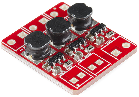
The circuit board controls all of the lighting, sensors, timing, and debugging sequences. A reliable circuit board couldn’t just be an Arduino and a breadboard. I decided to use OSH Park and OSH Stencils to fabricate inexpensive circuit boards. I ultimately went through seven revisions while we worked out the final design of the lotuses. This included adding additional lights, additional sensors, controls for EL wire, and better power management using an external buck converter.
This board has support for multiple high current petal LEDs driven by digital RGB pins (used for fading colors in and out using PWM) and in multiple voltages. The high current petal LEDs runs on 12V, which comes directly off the battery, the ATmega328p chip and stem LEDs run at 5V, and the pulse sensor runs at 3.3V.
To convert 12V to 5V I use a $3 switching voltage regulator from Electrodragon. This requires a +/- connection for both 12V in and 5V out. To convert 5V to 3.3V I used a linear voltage regulator soldered directly on the board, since the current requirements of the pulse sensor were around 20mA. The heat dissipated was negligible compared to the rest of the circuit.
I also added terminal connections for two 5 meter LEDs that wrapped around the tall lotus stem. We attached two 5 meter LED strips around the stems because when two people put their hands on the two pulse sensors, we need an easy way to show both heartbeats without one winning out over the other. When only one person’s hand in being measured, both 5 meter light strips show the same color, which makes it that much brighter for a single person.
Lastly, the two pulse sensors terminate their I2C wires directly on the board. I used two separate I2C channels instead of one to cut down on time. I could easily have put both pulse sensors on the same I2C connections, but that would’ve required both pull-up resistors on the SDA and SCL data lines as well as a rewrite of the timing functions for the sensor.
All of these terminations are made using 2.5mm and 3.5mm pitch screw terminals. In hindsight I would have used female JST-SM mounted connectors and ordered custom wires with JST-SM male connectors. I assumed the lowest common denomenator would be bare tinned wire, but all of the bare wires could easily have been switched over to polarized, latching connectors. This would have reduced over 90% of the field work I had to perform on boards, as their wire would fall out of the screw terminals due to not being screwed in with enough force.
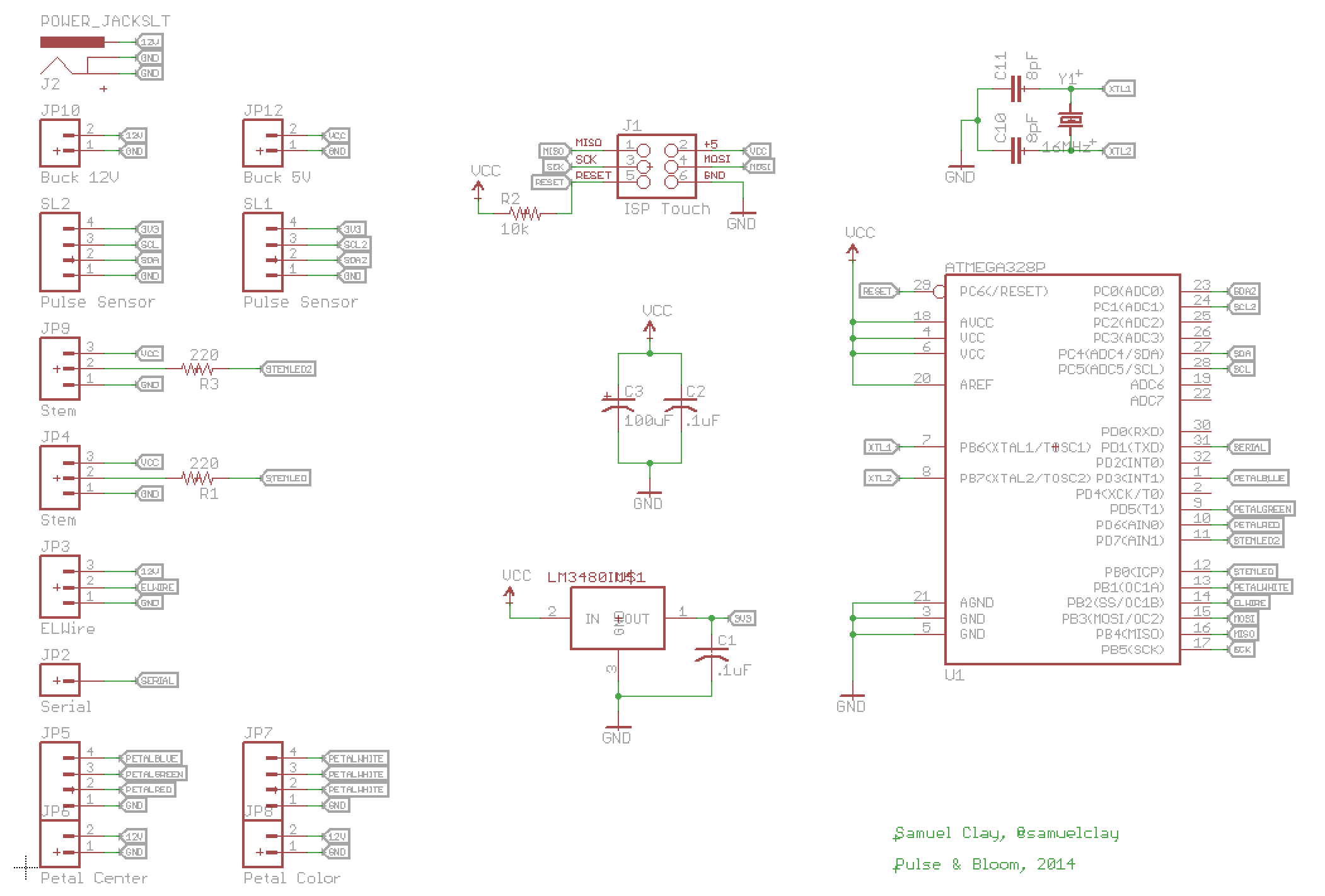
The board was laid out to be as big as a pack of gum. All of the 12V traces are thickened and isolated on the right side of the board. They are rated for 3 amps although they would end up only driving 1 amp on the playa.
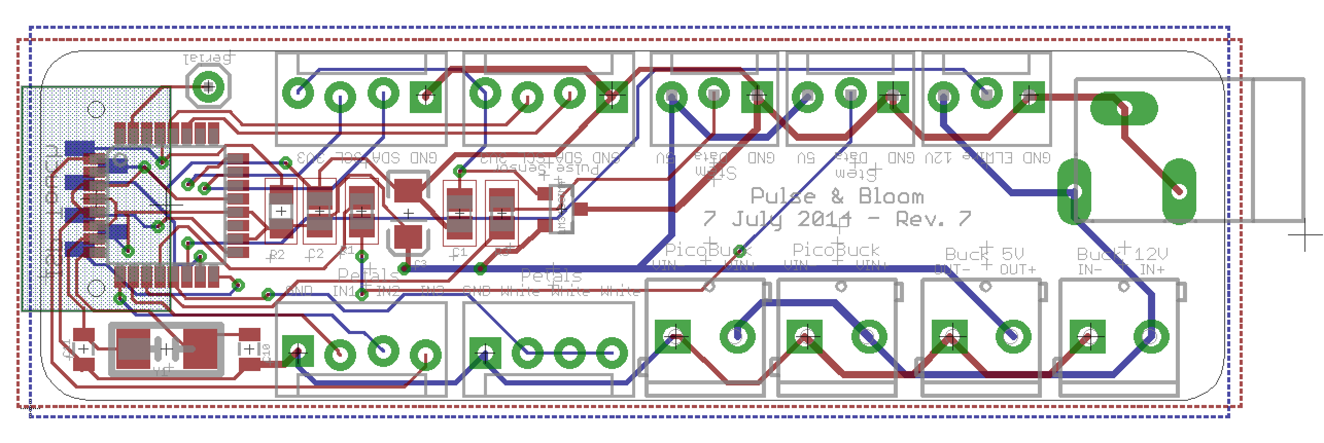
These boards are then stenciled with solder paste and populated with their chips and passive components.

An inexpensive hot plate is used to reflow the solder. The chip is in a TQFP package, which has a 0.5mm pitch between pins. This makes it nearly impossible to hand solder. This stencil and reflow technique works well and my yield stayed high at around 95%.

Finally, the board is ready to be populated with screw terminals.

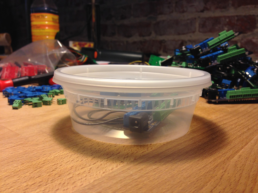
The final board in a dust-proof enclosure.
This was both the riskiest piece of the puzzle and also the most fun to build. In order to show your heartbeat on the lotus, I need to have a clear reading of your pulse. There are a fair number of issues with most off-the-shelf heartbeat sensors, including:
The first prototype I built suffered from the design affordance and reliability issues, although it worked pretty well in ideal conditions.
We ended up finding an IC by Silicon Labs called the Si114x, which uses three LEDs — two infrared and one visible — and a small QFN-10 sized light sensor. The original sensor we used was the Modern Device pulse sensor, which also provided firmware and ideas for a board layout. The folks at Modern Device were kind enough to offer advice on how they built their sensor and about how to fix the infrared LED issues we hit. I owe them beers for saving me from many more excruciating hours of trying to build sensors that don’t sense.

I built out a small PCB the size of a fingertip.

This tiny IC is a bit tricky to solder as it has no leads and the pins are extremely close together. My yield dropped to about 80%, but 4 out of every 5 pulse sensors I built worked perfectly the first time. If they failed, I would remount them on the hot plate and try wicking away any solder bridges I could find. This worked only about half the time. After that I gave up and now have a plastic cup full of broken pulse sensors.

Finally the sensor is hooked up and a tiny red light is emitted, letting people know where to put their fingers.

What turned these lotuses from flowers into gems are the high current LEDs mounted in the petals at the top. There are 9 of these high current LEDs per lotus, split into groups of three, each driven by a constant current driver.
If you were to look at one of these LEDs from a few feet away, you would immediately see spots in your eyes. They are extremely bright pinpoints of light. The fact that they are also full color and need a heatsink due to their brightness means that you won’t just find these in an easy package ready for plugging in.
Normally a single LED is powered by a single constant current driver. This driver can drive up to 1A of current at 12V. Because we were only using a single channel of color (blue) in the rest state, which is where the lotus spent most of its time, we could triple the number of LEDs driven by a single constant current driver.
When in use the petals glow amber, which uses two channels (100% red, 50% green) but only for a moment while at peak current. So while the peak current is above what this constant current driver is rated for, it’s only at peak and therefore within our tolerance.
Using a Chinese distributor, we bought these Sparkfun high current LEDs for $0.86 each instead of the full $15. However, we also bought 80 of Sparkfun’s PicoBucks to use as our constant current driver. While we could have built this ourselves to save money, buying 80 of something at $15 each is still only $1.2k, while building them ourselves would only have saved a few hundred dollars.

We bought 200 high current LEDs, all of which had to have their 6 anode and cathode connections soldered.
In order to connect 9 high current LEDs to the board, we need to drive them in groups of three. Each group has 6 connections: red, green, blue anodes, and red, green, blue cathodes. The wiring diagram for this setup can get a bit rats nesty, but the end result was fairly easy to work with, as the picobuck groups didn’t cross.

Finally, a shot of a complete picobuck with the wire connectors in the background.

The complete source code for Pulse & Bloom is on GitHub. There you can find the firmware used to program the main circuit board’s ATmega328p chip, as well as designs for the laser cut cowl that sits over the pulse sensor’s Si1143x IC.
The easiest way to read the firmware is to dive into src/pulse.cpp. It has all of the pulse and rest states and handles the high level logic.
The state machine that runs the entire routine is determined by a couple of critical measurements. The program takes a measurement of both pulse sensors and determines whether a finger is covering either of them and whether or not that finger has an active pulse going.
// Modes
void determinePlayerMode();
void determineFingerMode(int sensor1On, int sensor2On);
void resetStem(PulsePlug *pulse);
uint8_t adjustBpm(PulsePlug *pulse);
When there are no fingers on either of the pulse sensors, the program runs the rest state, which is a blue-topped lotus with a small blue snake running up and down the stem. The program is merely waiting for somebody to put their finger on a sensor.
// State: resting
void runResting();
void runRestStem();
void runRestStem(PulsePlug *pulse, int16_t currentLed);
void clearStemLeds(PulsePlug *pulse);
void beginPetalResting();
bool runPetalResting();
The firmware for the pulse sensor originally came from Modern Device’s pulse sensor. Before a heartbeat is shown an accurate measurement of a heartbeat needs to be read. In order to determine whether a heartbeat is found and at what speed, a number of light detection measurements are taken and analyzed.
Modern Device’s firmware simply finds the high frequency curve (the heartbeat) and the low frequency curve (the light sensors leveling out) and then use a simple peak and valley hueristic to determine the moment a heartbeat begins. This can take up to two or three seconds at first, so a bit of unwinding animation prepares you when you first put your finger on the sensor. I modified the firmware to account for multiple pulses on the same lotus and to have thresholds that worked better for the desert.
When a finger is detected, the stem snake lights shoot backwards up and down the lotus in prep for a heartbeat. This looks seamless as it clears the stem. This way a heartbeat doesn’t interrupt the rest state.
// State: end resting
void beginSplittingStem();
void runSplittingStem();
void runSplittingStem(PulsePlug *pulse, int16_t currentLed);
When a heartbeat is detected, it is first shot up the stem. The color is determined by how many pulse sensors are being used. 1 heartbeat shows amber. 2 heartbeats show in white and light red.
// State: stem rising
bool runStemRising(PulsePlug *pulse, PulsePlug *shadowPulse);
Once the heartbeat reaches the top of the stem, the petals then fill with light.
// State: petal rising
void beginPetalRising();
bool runPetalRising();
After a set delay, the petal slowly lose light while waiting for the next heartbeat.
// State: petal falling
void beginPetalFalling();
bool runPetalFalling();
Lots of debugging messages have been left in the code and are accessible using the Serial pin on the board. Just turn on USE_SERIAL, which is commented out at top. Note that this increases binary code size by about 2.5K. I wrote a lot of logging.
// Debugging
void printHeader();
void blink(int loops, int loopTime, bool half);
int freeRam ();While much of what I built above came out of knowledge I already had, learning how to power this large of an installation off just a battery was all new to me. I’m used to microelectronics that run off a coin cell or AA batteries.
First, in order to figure out how big of a battery we needed, we had to measure how much power we were taking. I hooked up an ammeter in series with a single lotus to measure the current draw. In rest state, a single lotus drew 0.75A at 12V. In the active pulsing heartbeat state, a single lotus drew 1.5A at 12V. Since a lotus spends 95% of its time at rest, we rounded the average current consumption to 1A.
Twenty lotuses at 1A at 12V meant we needed 240Ah to sustain a 12 hour night. A car battery was recommended, but car batteries can only discharge down to 80% without irreparable harm. However, a marine deep-cycle battery can go down to 20% without harm.
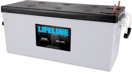
This 150 lb. battery has enough capacity, although we ended up adding a couple 6V batteries in series (to boost them to 12V) and then running them in parallel to offset some of the load.
A big issue we ran into was the voltage drop across the power lines. We placed the batteries on the edge of the installation, which meant some of the lotuses had 20 meters of wire between them and the battery. The voltage drop per 10 meter section is nearly 2V, which means that the voltage reaching the further lotuses was down to 7.5V.
The high current LEDs were not able to be smoothly driven at this low of a voltage, causing them to flicker. We determined that a voltage drop was responsible for the flickering, which got worse the further the lotus sat from the batteries. But when we discovered this the wires had already been trenched 6 inches beneath the playa. A day of work lost, but we sucked it up and ripped out all of the ground wiring to accommodate the battery which had to be moved into the center of the installation.
At the end of each night we had to bike out with a trike and carry all 300 lbs. of batteries back to camp, where they were hooked up to a 1 kW solar array, where they were charged at 48A over 6 hours.
Back at American Steel in Oakland, the lotus stems, bases, and petals were ready to be hooked up. These twenty lotus stems were bent by Heather. They range from 6ft to 16ft in length and each weighs 50 lbs.
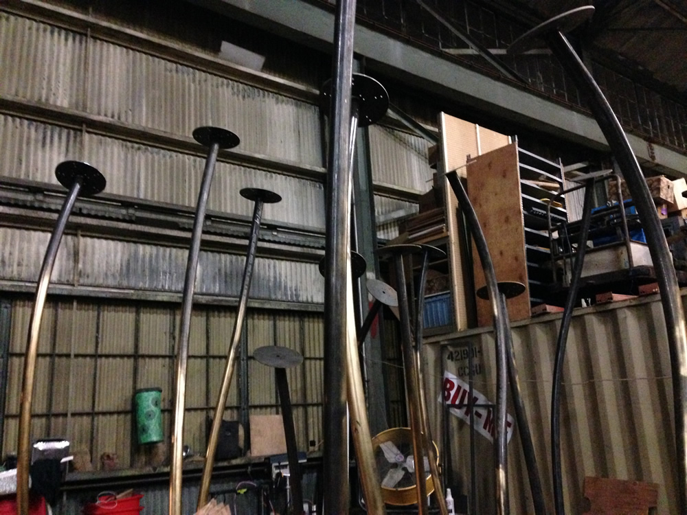
Such a heavy stem needs a larger base and heavy anchors to stay upright in the wind.

We placed the lily pad over the base to cover it up and then added all of the electronics. Lights, sensors, and circuit boards all had to be mounted.
This is a photo of our first complete lotus flower. Just compare its sheer size to Shilo.

Once we were confident that one lotus would successfully light we left the other 19 lotuses packed away for assembly on the playa.
We drove out in the biggest rental car I could get my hands on. Our minivan is full of electronics, bicycles, tents, costumes, coolers full of fruit and veggies, dry snacks, and water.

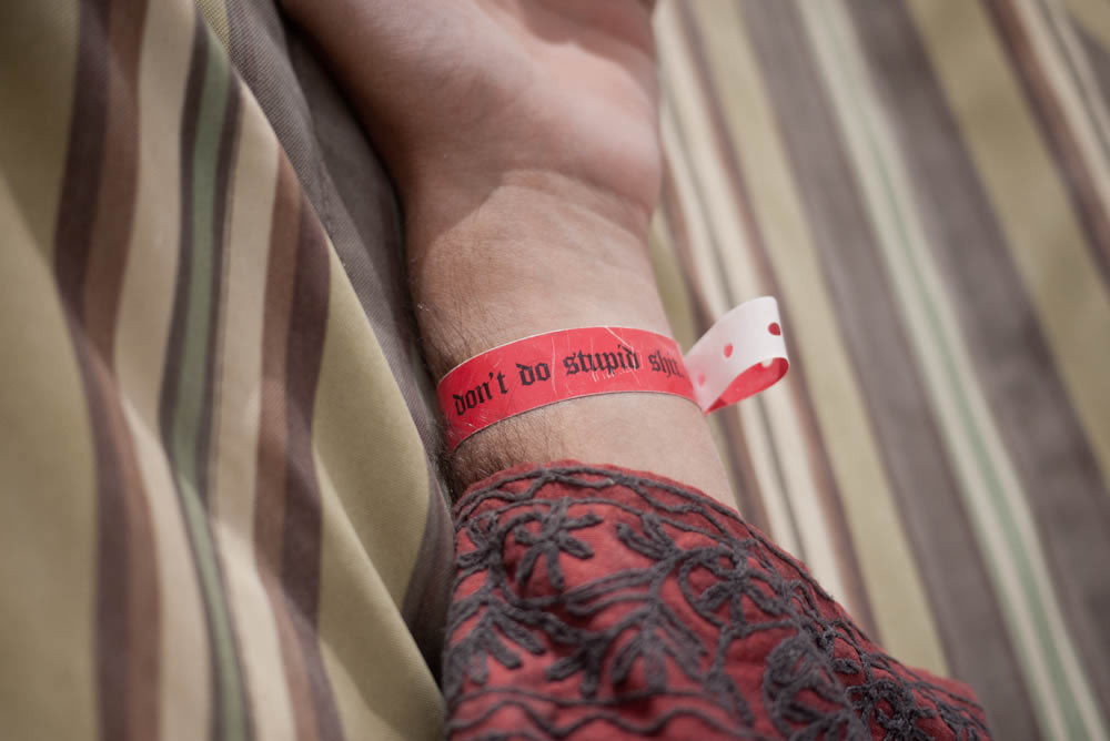
Since we were early arrival, they give you these red bracelets. They say Work hard, don’t do stupid shit.
The boards would accumulate dust on them everyday. Our plastic enclosures turned out to be too big for the holes we made in the platform. So we ended up using ziploc bags. These baggies stayed attached, but the only reason they didn’t cause any issues is that the boards worked just fine in the dust, as you can see here.
If dust was a real problem for the boards, then I would have spent a whole lot more time making a tight fitting enclosure and a hole for it that protects it both from the elements and from people.

The playa gets covered in dust storms regularly throughout the week. A particularly nasty dust storm is pictured here, eating our poor lotus flowers alive.

Although during the day when its not dust storming the lotuses offer a cozy respite from the heat of the playa.

The entire process lasted 4 months with 2.5 months of nearly full-time work on my part. I’m thrilled that I get to open-source both the process and the firmware. I hope others who build art installations can use some of my lessons learned here. I’m happy to answer any questions on Twitter.
See you next year on the playa!